TM-9-2815-213-34 - Page 7 of 192
*TM 9-2815-213-34
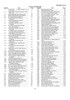
LIST OF ILLUSTRATIONS
Number
Title
Page
Number
Title
Page
1-1.
Model V8-300 .
.....
Engine Assembly
3/4 Left
3-12.
Piston Ring Gap Check.
....................................
3-7
Front View .
................................................
1-2
3-13.
Rod Side Clearance Check .
..............................
3-8
1-2.
Model V8-300 Engine Assembly 3/4
Right .
..
3-14.
Crankshaft Oil Seal-Removal/Installation.
.........
3-9
Rear View
................................................
1-3
3-15.
Front Cover Bore Alinement Check .
.................
3-9
1-3.
Engine Assembly Rear Sectional View .
........
1-6
3-16.
Front Cover to Block Alinement Check .
............
3-9
2-1.
Exhaust Manifold-Removal/Installation .
........
2-4
3-17.
Drive Gear Backlash Check .
............................
3-10
2-2.
Oil Cooler-Removal Installation .
....................
2-5
3-18.
Camshaft End Play Check .
..............................
3-11
2-3.
Engine Rebuild Stand-Removal
/ ...................
3-19.
Crankshaft Gear Backlash Check .
....................
3-11
Installation.
.................................................
2-5
3-20.
Crankshaft Adapter Tightening Sequence .
.......
3-12
2-4.
Fan Hub and Bracket Assembly-.
..................
3-21.
Flywheel Housing Concentricity Check
...........
3-13
Removal/Installation .
................................
2-5
3-22.
Flywheel Tightening Sequence .
........................
3-14
2-5.
Thermostat Assembly-Removal
/ ...................
3-23.
Flywheel Bearing Bore and Wobble Limits
3-14
Installation .
................................................
2-6
3-24.
Tappet Assembly Tes
t ......................................
3-15
2-6.
Drive Pulleys and Vibration Damper- .
...........
3-25.
Cylinder Head in Holding Fixture
.....................
3-16
Removal/Installation .
.................................
2-6
3-26.
Valve Assemblies-Removal/Installation .
...........
3-16
2-7.
Water Pump Assembly-Remova
l ..................
3-27.
Injector Sleeves-Removal/Installation .
.............
3-16
Installation .
................................................
2-6
3-28.
Crosshead Guide-Removal/Installation.
............
3-16
2-8.
Air Intake Crossover and Preheater .
.............
3-29.
Valve Seat Removal Sectional View .
................
3-17
Assembly-Removal/Installation.
.................
2-7
3-30.
Injector Sleeve Holder Installation .
...................
3-17
2-9.
Intake Manifold, Fuel Pump and Fuel .
...........
3-31.
Injector Tip Protrusion Measurement .
...............
3-17
Lines-Removal/Installation .
.......................
2-7
3-32.
Valve Head and Collet Check .
..........................
3-18
2-10.
Water Crossover Pipe and Lifting Eye .
.........
3-33.
Crosshead Guide Check
.................................
3-18
Removal/Installation .
................................
2-8
3-34.
Valve Guide Check .
..........................................
3-18
2-11.
Oil Dipstick Tube Assembly-Removal
/ ..........
3-35.
Valve Spring Test
............................................
3-18
Installation .
................................................
2-8
3-46.
Valve and Injector Counterbore Measure-
.
2-12.
Cylinder Head Covers-Removal/ .
..................
ments .
...............................................................
3-19
Installation.
.................................................
2-9
3-37.
Cylinder Head Regrooving .
...............................
3-19
2-13.
Crankcase Breather Tube Removal/ .
............
3-38.
Valve Guide Installation .
...................................
3-20
Installation.
.................................................
2-9
3-39.
Crosshead Guide Installation- .
..........................
3-20
2-14.
Push Rod Cavity Covers-Removal/ .
..............
3-40.
Injector Sleeve Installation .
..............................
3-20
Installation.
.................................................
2-9
3-41.
Injector Sleeve Rolling-Upper Portion .
..............
3-21
2-15.
Rocker Arms and Push Rods-Removal/.
.......
3-42.
Injector Sleeve Rolling-Lower Portion .
..............
3-21
Installation.
.................................................
2-10
3-43.
Injector Sleeve Seat Cutting.
.............................
3-21
2-16.
Injector Clamps Removal/Installation .
...........
2-10
3-44.
Valve Seat Insert Counterbore .
........................
3-21
2-17.
Fuel Injector and Hold-Down Clamp.
.............
2-10
3-45.
Intake Valve Port Swirl Plate Installation.
..........
3-22
2-18.
Valve Crossheads-Removal/Installation .
.......
2-11
3-46.
Valve Seat Insert Peering .
................................
3-22
2-19.
Cylinder Head-Removal/,Installation .
............
2-11
3-47.
Valve Seat Test.3.
.............................................
3-22
2-20.
Valve and Injector Tappets-Removal
/ ...........
3-48.
Cylinder Head Tightening Sequence .
...............
3-23
Installation.
.................................................
2-11
3-49.
Fuel Injector PT (Type C).
.................................
3-24
2-21.
Flywheel-Removal/Installation.
......................
2-12
3-50.
Injector Cup-Removal/Installation .
....................
3-24
2-22.
Crankshaft Adapter-Removal/Installation
2-12
3-51.
Injector Link-Removal/Installation .
....................
3-24
2-23.
Flywheel Housing-Removal/Installation.
........
2-13
3-52.
Plunger Seat Pattern .
.......................................
3-24
2-24.
Camshaft Gear, and Spacer Plate- .
..............
3-53.
Fuel Injector-Exploded View.
.............................
3-26
Removal/Installation .
.................................
2-13
3-54.
Injector Check Ball Seating .
..............................
3-26
2-25.
Oil Pan-Removal/Installation .
........................
2-13
3-55.
Injector Body 0-Ring Installation .
......................
3-26
2-26.
Oil Pump Assembly-Removal/Installation
2-13
3-56.
Injector Body and Plunger Markings .
................
3-27
2-27.
Front Cover-Removal/Installation .
.................
2-14
3-57.
Injector Cup Markings .
.....................................
3-27
2-28.
Connecting Rod and Piston Assembly- .
........
3-58.
Injector Plunger Seat Test.
................................
3-27
Removal/Installation .
.................................
2-14
3-59.
Injector Test Stand-.
..........................................
3-29
2-29.
Crankshaft and Main Bearings-Removal/.
.....
3-60.
Alining Timing Wheel and Pointer .
....................
3-29
Installation.
.................................................
2-14
3-61.
Hydraulic and Air Valves .
..................................
3-29
3-1.
Camshaft Bushing Removal .
........................
3-1
3-62.
Air Pressure Adjustmen
t ...................................
3-30
3-2.
Cylinder Sleeve Removal .
............................
3-1
3-63.
Master Injector Installation- .
..............................
3-30
3-3.
Main Bearing Bore Alinement Check.
............
3-2
3-64.
Fuel Inlet Installation .
........................................
3-30
3-4.
Cylinder Sleeve Seals Installation .
................
3-2
3-65.
Injector Mounted in Test Stand .
........................
3-30
3-5.
Crankshaft Dimensions .
................................
3-4
3-66.
Test Stand Air Pressure Connection .
................
3-31
3-6.
Crankshaft End Clearance Check .
................
3-5
3-67.
Load Cell Test .
..................................................
3-31
3-7.
Bearing Cap to Block Clearance Check .
.......
3-5
3-68.
Ball Seat Resurfacing.
.......................................
3-32
3-8.
Side Bolt Tightening Sequence .
....................
3-5
3-69.
Orifice Hole Burnishing Tool Installation .
..........
3-33
3-9.
Piston and Ring Assembly .
...........................
3-6
3-70.
Orifice Plug Burnishing .
....................................
3-33
3-10.
Connecting Rod Check .
................................
3-6
3-72.
Injector Push Rod Timing .
................................
3-33
3-11.
Ring Groove Wear Check .
............................
3-7
3-72.
Air Compressor Drive Gear Timing Mark .
.........
3-37
iii
Back to Top

