TM-9-2815-213-34 - Page 9 of 192
*TM 9-2815-213-34
CHAPTER 1
INTRODUCTION
Section I. General
1-1. Scope
a
.
This technical manual contains instruction for
direct and general support maintenance of the Cummins
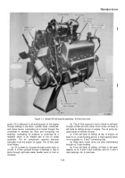
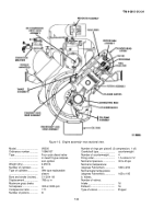
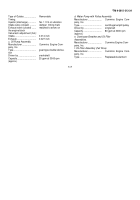
Diesel Engine, Model V8-300, (fig. 1-1 and 1-2). It
contains
descriptions
of,
and
procedures
for,
disassembly, inspection, repair, rebuild, and assembly of
the engine.
b
.
Appendix A contains a list of current refer ences,
including supply manuals, forms, technical manuals, and
other available publications applicable to the engine.
c
.
Appendix B lists repair parts, special tools, and
test equipment required for the performance of direct
and general support maintenance of the engine.
1-2.
Forms and Records
Maintenance forms, records, and reports which are to be
used by maintenance personnel at all maintenance
levels are listed in and prescribed by TM 38-750.
1-3.
Reporting of Equipment Publication
Improvement
The
reporting
of
errors,
omissions,
and
recommendations for improving this publication by the
individual user is encouraged. Reports should be
submitted on DA Form 2028, Recommended Changes to
Publications, and forwarded direct to the Commanding
General,
U.S.
Army
Tank-Automotive
Command
Attention: ASMTA-4, Warren, MI 48090.
Section II. Description and Data
1-4. Description
a.
General.
(1
) In this manual the following terms will be used to
identify the location for engine parts and assemblies:
(a)
Front-
fan end of engine.
(b)
Rear-
flywheel
end of engine.
(c)
Right and Left-
are
identified as viewed from
the rear.
(2
) The model V8-300 diesel engine is as eight
cylinder,
V-type,
Valve-in-head,
water
cooled,
compression-ignition engine, using the four stroke cycle
principle of operation. The four strokes consist of intake,
compression, power and exhaust. Intake and exhaust
valves, and fuel injectors, are operated from a single
camshaft. The intake stroke of the cycle brings filtered,
heated air to the cylinders. The compression stroke
compresses the air (17:1 compression ratio) to 500-600
p.s.i,
and
raises
the
cylinder
temperature
to
approximately 1000 degrees Fahrenheit. During the top
of the compression stroke and start of the power stroke,
a metered charge of diesel fuel is injected into the
cylinders. The high temperature within the cylinders
ignites the diesel fuel resulting in the power stroke. The
fourth stroke of the cycle exhausts the burned
gases from the cylinders. Proper engine operation
depends upon the high compression of the intake air and
the timed injection of the correct measure of diesel fuel
into the cylinder.
b.
Engine Assembly.
The model V8-300 engine
(fig. 1-1 and 1-2) is a diesel eight cylinder V-type, valve in
head, water cooled, compression ignition engine. The
engine is rated 300 horsepower at 3000 rpm and will
operate on diesel fuel.
c.
Engine Systems.
(1
) Fuel System. The system consists of a filter, fuel
pump with governor, fuel passages, and injectors (one
for each cylinder). The system is designed so that the
volume of liquid flow is proportionate to the fluid
pressure, the time allowed to flow, and the size of the
orifice fuel flows through. The pump draws fuel from the
vehicle supply tank and delivers it to each injector. A
governor controls the flow of fuel from the gear pump, as
well as the idle and maximum engine speed.
(2)
Lubrication System.
All working parts of the
engine are pressure lubricated. Oil is supplied by a dual-
type gear driven lubricating pump located below the
crankshaft and driven by the crankshaft gear. On
completion of the lubrication cycle, oil is accumulated in
the oil pan sump by gravity and is drawn from this sump
by the oil
1-1
Back to Top

