TM-9-2815-220-34 - Page 151 of 532
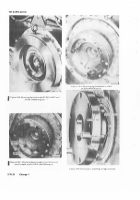
Figure 2·1±4.
Font faN TOwer ±uEl injEc²I³n tUb´ CAmp Bk´µ
Lo¶·¸ion.
(3)
InstalL oiL seal
¹5º
±n o±l seal hous±ng
»4¼
w±th
Lip of oi² seal toward the bottom of the hous±ng, aND
the felt toward the top.
(4) lnstaL± fAN drive o. sE²± houSINg ³4´ UsINg
nµw gask¶t,
On
faN drive hou·INg covµR
aNd
·µCu¸µ
wITH ¹Ix bOº»· ¼nd Flat w½shµ¾s ¿2ÀÁ lÂsüJJ ±ÄÅkINg
wÆÇe¿!ÈÉ
½5¾
³nstaLl cool´ng Fans and cool´ng µAn vanes
(paRa
2-21b).
2-¿9À
Fuel Injector TUbes
a± RemovAl±
(²³
·emoVe cool±ng fan vanes, cool±ng faNs, en-
g¸ne UPper co¹erS, and cool±Ng fan sHroUdº »efer to
pa¼agraPh
2-´LAµ
¶2)
·emo½e fuel ±njector t¾be c¿aMps and
tubesÀ ·efer to paragraph
2·2²a¸
b¹ Instº»¼ºTion½
¾1³
ÁnstalL µÂel ´nJector tÂbes and cLamps (para
2¿2Àb)Á
Â
¾2³
Check for µuel leaKs (parA
2Ã21B³Ä
(3Á
Ãnstall cooLing fan shRoud, eng±ne upper
co½ersÄ cooL±Ng µans and fan vaNes Åpara
2Å2²Æ)Ç
ÂÃÄ0Å
ThRo±²le Linkage and Manua³ Fue´
SHu±-of µoDs
a± RemOvºÈÉ
Ê1³
»emo½e cool±ng µan vanes anD cooL±ng fans
ÆeF eÇ to paraGÈaph
ËÅ21a½
Ì2³
»emoVe cotteÉ Êin anD µLat WasheR Ëf´gÌ
Ë¿²²6)
anD D±sconnecT manÍal µUel shutÎoff roD as-
semblyÌ Ï±scard cotter piNÐ ·emo½e selµÑÒocÓiNg
nut, anD machine bolt, and d±scoNnect adÔÕstable
rod.
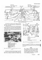
ÆM ÇÈÉ81ÊÈÉÉËÈÌÍ
Fig1±re
²-³´5µ
DIscm²³´RµtI³¶g
"'±
<"<Ht¶¸cdItt{
M±·³¸¶wl.L¹·Cº S»Tu¼½of¾
RD
ÎÏd
¿ÀÁÂÃÄÅ/Ƴ/ÇÈÉ
Thm¹º/p l'L»D¼
(3Ð
»emo½e seLfÖLoc×ing nut and machine boLt
(figº
2Ų1ͳ
anD ReØo½e aDJustaBLe throttLe rodÙ
»emo½e tWo selfÚloÛÓ´ng nuts, mach´ne Bolts anD
one ÜaT waSheÝ and remoÞe throttle operatßng
leveà rodá
ÊËGÌÍÎ
½¾J ¿6À
ÏÐÑOUÒÓÔg ÕÍ ËÖ¶×ØaÙºÚÖÆg
ÎDJÑsÒÎÓÔÕ Ö×Ø
a
ÁÂ
ÛܶÝÞßàe
ÙPÚRÛÜÝNg Þßvàá â×Øã
(3.1)
Dµ±µÃÊdË
•
fGUÃE 2ÄÅÆÇÈ ÉÊ
ËÌÍÌÎÌÏ
ä
åhæçGè é
êë7ì
Back to Top


