TM-9-2815-225-34-P - Page 164 of 736
TM 9-2815-225-34&P
0013 00
0013 00-4
CYLINDER BLOCK (Contd)
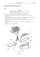
ASSEMBLY
1.
Apply pipe sealant to threads of new expansion plug (6). Install expansion plug (6) on cylinder
block (14). Tighten plug (6) 30 lb-ft (41 N
•
m).
2.
Apply pipe sealant to threads of two new expansion plugs (12). Install expansion plugs (12) on
cylinder block (14). Tighten expansion plugs (12) 45 lb-ft (61 N
•
m).
3.
Apply pipe sealant to threads of four new expansion plugs (9). Install expansion plugs (9) on
cylinder block (14). Tighten expansion plugs (9) 15 lb-ft (20 N
•
m).
4.
Apply pipe sealant to threads of five new expansion plugs (13). Install expansion plugs (13) on
cylinder block (14). Tighten expansion plugs (13) 35 lb-ft (48 N
•
m).
5.
Apply pipe sealant to threads of new expansion plug (10). Install expansion plug (10) and washer
(11) on cylinder block (14). Tighten expansion plug (10) 70 lb-ft (95 N
•
m).
6.
Install cylinder sleeve shims (2), as required, on cylinder sleeve (1).
7.
Install new cap (7) on cylinder block (14).
CAUTION
Do not lubricate O-rings until ready to install assembled
cylinder sleeve. O-rings will increase in size once in contact
with OE/HDO 10 lubricating oil for more than 10 minutes.
Prior to installing a cylinder sleeve, apply a bead of inner
sealer on counterbore of cylinder sleeve flange. Do not use an
excessive amount of sealer. Excessive amounts can cause
problems in cooling system.
Do not permit lubricating oil, once applied to O-rings, to come
in contact with liner sealant. Oil will prevent sealant from
adhering to liner flange and counterbore contact surface.
NOTE
Diameter of applied sealer bead must be at least 3/64 in.
(1.2 mm) and not more than 1/16 in. (1.6 mm) wide. Cylinder
sleeve must be installed within 5 minutes after sealer has been
applied.
All cylinder sleeves are installed the same way. The following
procedure covers one cylinder liner installation.
8.
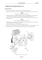
Install new gasket (3) with chamfer down in top groove on cylinder sleeve (1).
9.
Install new black O-ring (5) on center groove of cylinder sleeve (1).
10.
Install new red O-ring (4) on bottom groove of cylinder sleeve (1).
11.
Apply OE/HDO 10 lubricating oil to gasket (3) and O-rings (4) and (5) and install assembled
cylinder sleeve (1) on cylinder block (15) within 10 minutes.
12.
Position cylinder sleeve (1) on bore of cylinder block (14) by hand and push downward with one
quick stroke.
13.
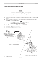
Using cylinder sleeve driver and mallet, drive flange against counterbore edge.
14.
Install two cylinder sleeve clamps on cylinder block (14) and cylinder sleeve (1). Tighten clamps
50 lb-ft (68 N
•
m).
15.
Using gauge block, check protrusion of cylinder sleeve (1). Amount of protrusion must not exceed
0.003–0.006 in. (0.076–0.152 mm).
16.
Remove cylinder sleeve clamps from cylinder block (14) and cylinder sleeve (1).
17.
Repeat steps 7 through 15 for remaining cylinder sleeves.
Back to Top


