TM-9-2815-225-34-P - Page 162 of 736
TM 9-2815-225-34&P
0013 00
0013 00-2
CYLINDER BLOCK (Contd)
DISASSEMBLY
NOTE
Rotate the engine so cylinder sleeves are facing up. All cylinder
sleeves are removed the same way. The following procedure
covers one cylinder sleeve.
1.
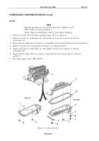
Using universal cylinder sleeve puller, remove cylinder sleeve (1) from cylinder block (11).
NOTE
If shims are used under cylinder sleeve, do not discard shims.
Using a micrometer or equivalent, measure and record
thickness of six shims and tag the location of each cylinder
sleeve and shims to aid in assembly.
2.
Remove red O-ring (4), black O-ring (5), gasket (3) and shims (2) from cylinder sleeve (1). Discard
red O-ring (4), black O-ring (5), and gasket (3).
3.
Perform steps 1 and 2 for remaining cylinder sleeves.
4.
Remove sixteen expansion plugs (6) from cylinder block (11). Discard expansion plugs (6).
5.
Remove expansion plug (9) and washer (10) from cylinder block (11). Discard expansion plug (9).
6.
Remove six dowel pins (12) from cylinder block (11).
7.
Remove six cam follower dowel pins (8) from cylinder block (11).
8.
Using hammer and punch, remove cap (7) from cylinder block (11). Discard cap (7).
CLEANING AND INSPECTION
1.
For general parts cleaning information, refer to CLEANING, WP 0051 00.
2.
For general parts inspection information, refer to INSPECTION, WP 0051 00.
NOTE
Replace any part that does not pass visual inspection or that is
outside specified wear limits.
Cylinder block must be checked on a flat surface to prevent
distortion and incorrect measurements.
Do not inspect cylinder block on maintenance stand.
3.
Using crack detector dye, inspect cylinder sleeves (1) and cylinder block (11) for cracks.
4.
Inspect cylinder sleeves (1) for excessive corrosion, erosion, and pits. Maximum pit depth is .0625
in. (1.6 mm).
5.
Inspect underside top flange of cylinder sleeves (1) for dents, pitting, or worn surfaces. If surface
cannot be smoothed out with 290-grit emery cloth, discard cylinder sleeve (1).
6.
Using dial bore gauge, measure inside bore of cylinder sleeve (1). Maximum inside diameter is
5.505 in. (13.983 cm).
7.
Inspect all cylinder block (11) plug holes and threaded holes for damaged threads and surfaces.
8.
Inspect all dowel pins (8) and (12) for cracks or distortion.
9.
Using straightedge and 0.02 in. (0.51 mm) feeler gauge, check cylinder block (11) for flatness. If
gap between straightedge and cylinder block (10) is more than 0.02 in. (0.51 mm), cylinder block
(11) must be milled.
Back to Top


