TM-9-2815-225-34-P - Page 380 of 736
TM 9-2815-225-34&P
0042 00
0042 00-26
CYLINDER BLOCK COMPONENTS INSTALLATION (Contd)
FLYWHEEL, FLEXPLATE, AND FLYWHEEL HOUSING (Contd)
NOTE
Big Cam III engines are equipped with a flexplate-type
flywheel with retaining plate and washer bearing.
Perform steps 21 and 22 for Big Cam III only.
21.
Apply a thin coat of lubricating oil to threads of screws (7) and face of washers (6)
22.
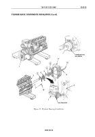
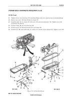
Install retaining plate (2), flexplates (3), flywheel (4), and washer bearing (5) on crankshaft (1)
with six screws (7) and washers (6). Tighten screws (7) 200–220 lb-ft (271–298 N
•
m) in sequence
shown in figure 15.
NOTE
Perform steps 23 through 27 for Big Cam I only.
23.
Install two 5/8-18 x 6 in. guide studs in opposite holes on crankshaft (1) until fully seated.
24.
Apply lubricating oil to threads of screws (11) and face of washers (10). Allow excess oil to drain
from screw threads.
25.
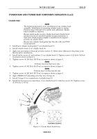
Install flywheel (9) and spacer gear (8) on crankshaft (1) with four screws (11) and washers (10).
Tighten screws (11) hand-tight in sequence shown in figure 16.
26.
Remove two 5/8-18 x 6 in. guide studs from crankshaft (1).
27.
Install two remaining screws (11) and washers (10) on flywheel (9). Tighten screws (11) 70 lb-ft
(95 N
•
m) then 140 lb-ft (190 N
•
m) and finally 200–220 lb-ft (271–298 N
•
m) in sequence shown in
figure 16.
NOTE
The flywheel must be pushed toward front of engine to remove
crankshaft end clearance when crankshaft is rotated and
measurements are taken. If total indicator readings exceed
limits, remove flywheel; clean flywheel and crankshaft flange
faces, install, and repeat runout checks.
Perform steps 28 through 31 for Big Cam I only.
28.
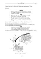
Install dial gauge attachment and dial indicator on flywheel housing (12).
29.
Position contact tip of dial indicator against wide diameter of flywheel (9) bore and set dial
indicator to zero. Rotate crankshaft (1) one complete revolution. Total indicator reading must not
exceed 0.005 in. (0.127 mm).
30.
Inspect flywheel (9) face runout and install or reposition dial indicator on flywheel housing (12).
31.
Position contact tip of dial indicator against face of flywheel (9) as close to outside diameter as
possible. Rotate crankshaft (1) one complete revolution. Total indicator reading must not exceed
0.005 in. (0.127 mm).
Back to Top

