TM-9-2815-225-34-P - Page 383 of 736
TM 9-2815-225-34&P
0042 00
0042 00-29/30 blank
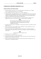
CYLINDER BLOCK COMPONENTS INSTALLATION (Contd)
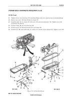
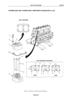
Figure 18. Oil Pan Installation.
BIG CAM I
BIG CAM III
1
20
19
18
17
21
22
4
37
36
35
12
24
34
33
32
8
28
9
17
29
30
31
27
26
25
23
22
6
5
15
14
16
2
3
4
5
6
7
8
9
10
13
8
9
12
END OF WORK PACKAGE
OIL PAN (Contd)
21.
Tighten nut on oil suction hose (25) mounting flange until nut is against stop on mounting flange.
22.
Remove one screw (12) from left side of oil pan (37).
23.
Install bracket (31) on oil pan (37) with screw (32) and new lockwasher (33). Tighten screw (32)
35–40 lb-ft (41–48 N
•
m).
24.
Position clamp (29) on oil suction hose (25).
25.
Position spacer (30) between bracket (31) and clamp (29).
26.
Install screw (28), new lockwasher (8), washer (9), and nut (34) on bracket (31). Tighten screw (28).
11
Back to Top


