TM-9-2815-225-34-P - Page 375 of 736
TM 9-2815-225-34&P
0042 00
0042 00-21
CYLINDER BLOCK COMPONENTS INSTALLATION (Contd)
FRONT GEAR COVER (Contd)
12.
Install dial indicator on front of crankshaft and position tip of dial indicator against inner surface
of crankshaft seal bore.
13.
Turn dial of indicator to zero.
14.
Rotate crankshaft one complete revolution. Reading on dial indicator shows difference. If total dial
indicator reading exceeds 0.010 in. (0.254 mm), remove, clean, and relocate between common
centers.
15.
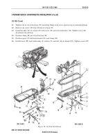
Remove shim pack (6) and seal (7) from camshaft support (5).
16.
Install camshaft support (5) on gear cover (11) and hold against end of camshaft. Ensure camshaft
is pushed against cylinder block (14).
17.
Using feeler gauge, measure space between mounting flange of camshaft support (5) and gear
cover (11). Use measurement to determine thickness of shim pack (6) needed to provide
0.008–0.130 in. (0.203–3.302 mm) clearance. Shim packs (6) are available in four different
thicknesses.
18.
Remove camshaft support (5) from gear cover (11).
19.
Install shim pack (6) and new seal (7) on camshaft support (5).
20.
Install camshaft support (5), shim pack (6), and seal (7) on gear cover (11).
NOTE
Perform step 21 for Big Cam I only.
21.
Install three screws (4), new lockwashers (18), and washers (17) on camshaft support (5). Tighten
screws (4) 15–20 lb-ft. (20–27 N
•
m).
NOTE
Perform step 22 for Big Cam III only.
22.
Install three screws (4) on camshaft support (5). Tighten screws (4) 15–20 lb-ft. (20–27 N
•
m).
Figure 12. Front Cover Installation.
20
19
1
2
1
2
3
18
17
8
16
15
4
5
6
7
9
10
11
12
13
14
13
Back to Top


