TM-9-2815-225-34-P - Page 367 of 736
TM 9-2815-225-34&P
0042 00
0042 00-13
CYLINDER BLOCK COMPONENTS INSTALLATION (Contd)
OIL PUMP (Contd)
NOTE
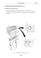
Perform step 7 for Big Cam I only.
7.
Install oil pump (13) and new gasket (14) on cylinder block (1) with five new lockwashers (12), two
short bolts (11), and three long bolts (10). Tighten bolts (10) and (11) 40 lb-ft (54 N
•
m).
8.
Install dial indicator and dial gauge attachment on front of cylinder block (1), and position tip of
dial indicator against tooth of pump drive gear (8).
9.
Rotate pump drive gear (8) as far as it will freely move. Ensure that camshaft gear (15) does not
move.
10.
Turn dial indicator to zero.
11.
Rotate pump drive gear (8) in opposite direction. The reading of dial indicator shows the amount
of backlash between gears. Minimum backlash is 0.002 in. (0.051 mm) and maximum backlash is
0.016 in. (0.406 mm). Replace pump drive gear if not within specifications.
Figure 8. Oil Pump Installation.
OIL PUMP GEAR BACKLASH CHECK
8
9
1
1
15
14
13
12
10
11
8
DIAL
INDICATOR
Back to Top

