TM-9-2815-225-34-P - Page 360 of 736
TM 9-2815-225-34&P
0042 00
0042 00-6
CYLINDER BLOCK COMPONENTS INSTALLATION (Contd)
CAMSHAFT
CAUTION
The oil grooves on thrust washer must be installed facing
camshaft gear, or thrust washer failure will result.
NOTE
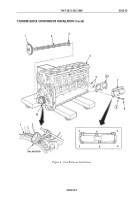
Four camshaft pilot tools may be used to assist with camshaft
installation.
1.
Using high-pressure lubricant, coat both sides of thrust washer (3) and slide thrust washer (3)
over end of camshaft (2) until seated next to camshaft gear (1).
NOTE
Lubricate cam lobes with high-pressure lubricant.
2.
Apply high-pressure lubricant to camshaft (2) lobes.
3.
Install camshaft (2) in cylinder block (4).
4.
Line up timing mark O on camshaft gear (1) with timing mark O on crankshaft gear (10) and fully
seat camshaft (2) and thrust washer (3) against cylinder block (4). Remove camshaft pilot tools
from camshaft (2), if utilized.
5.
Install dial indicator on front of cylinder block (4), and position tip of dial indicator against tooth
on camshaft gear (1).
6.
Rotate camshaft gear (1) as far as it will freely move. Ensure crankshaft gear (10) does not move.
7.
Turn dial indicator to zero.
8.
Rotate camshaft gear (1) in opposite direction as far as it will freely move. Dial indicator reading
shows amount of backlash between gears.
9.
Normal backlash is 0.004–0.016 in. (0.102–0.406 mm) between new camshaft gear (1) and new
crankshaft gear (10). Minimum backlash for new camshaft gear (1) is 0.002 in. (0.051 mm). Gears
will begin to make noise if backlash exceeds 0.010 in. (0.254 mm). If noise is acceptable, do not
replace gears unless backlash exceeds 0.020 in. (0.508 mm).
NOTE
Perform steps 10 and 11 to install any one of the three cam
follower assemblies. Repeat steps 10 and 11 as required to
install each additional cam follower assembly.
Gaskets must be the same thickness as those removed. Total
gasket thickness must be 0.014–0.080 in. (0.356–2.032 mm).
10.
Install new cam follower housing gasket (6) on two dowel pins (5).
NOTE
Strike housing with soft-nose hammer to push it onto dowel
pins on cylinder block.
11.
Install cam follower housing (7) with six screws (8) and new lockwashers (9) on cylinder block (4).
Tighten screws (8) 15 lb-ft (20 N
•
m) in tightening sequence shown in figure 4, and then tighten
30–35 lb-ft (41–48 N
•
m) in sequence shown in figure 4.
Back to Top

