TM-9-2815-225-34-P - Page 358 of 736
TM 9-2815-225-34&P
0042 00
0042 00-4
CYLINDER BLOCK COMPONENTS INSTALLATION (Contd)
CRANKSHAFT AND MAIN BEARINGS (Contd)
10.
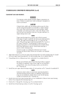
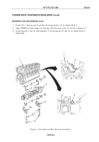
Using rubber mallet, strike bearing caps (2) into position on cylinder block (1).
11.
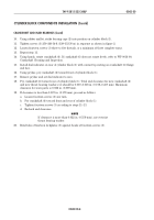
Tighten screws (3) 250–260 lb-ft (339–353 N
•
m) in sequence as shown in figure 2.
12.
Loosen fourteen screws (3) three to five threads, or a minimum of three complete turns.
13.
Repeat step 11.
14.
Using hands, rotate crankshaft (6). If crankshaft (6) does not rotate freely, refer to WP 0016 00,
Crankshaft Cleaning and Inspection.
15.
Install dial indicator on rear of cylinder block (1) with contact tip resting on crankshaft (6) flange
end face.
16.
Using prybar, pry crankshaft (6) toward front of cylinder block (1).
17.
Remove prybar and set dial indicator to zero.
18.
Pry crankshaft (6) toward rear of cylinder block (1). Total end clearance for new crankshaft (6)
and new thrust bearing washers (4) should be 0.007–0.018 in. (0.178–0.457 mm). Maximum
clearance for worn parts is 0.022 in. (0.559 mm).
19.
If clearance is less than 0.007 in. (0.178 mm), proceed as follows:
a.
Loosen fourteen screws (3) one turn.
b.
Pry crankshaft (6) toward front and rear of cylinder block (1).
c.
Tighten fourteen screws (3) according to steps 11–13.
d.
Recheck end clearance.
NOTE
If clearance is more than 0.022 in. (0.559 mm), use oversize
thrust bearing washer.
20.
Bend tabs of fourteen lockplates (5) against heads of fourteen screws (3).
Back to Top


