TM-9-2815-225-34-P - Page 362 of 736
TM 9-2815-225-34&P
0042 00
0042 00-8
CYLINDER BLOCK COMPONENTS INSTALLATION (Contd)
PISTONS AND CONNECTING RODS
NOTE
Perform steps 1 through 18 to install any one of the six piston,
connecting rod, and bearings assemblies. Repeat for remaining
piston, connecting rod and bearing assemblies.
Parts are not interchangeable. Do not mix parts from one
assembly with another. Always replace bearing halves in pairs
(upper and lower). Check for marks on crankshaft to determine
bearing size. If there are no marks, use standard size parts.
1.
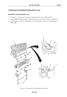
Using piston ring expander, install two new compression rings (1) and (3) and two new piston
rings (2) and (4) on piston and connecting rod assembly (5). Stagger ring gaps so they are not in
line with each other or with piston pin.
2.
Install new upper rod bearing half (7) on piston and connecting rod assembly (5). Ensure oil hole
in bearing half (7) lines up with oil hole in connecting rod (6).
3.
Install new lower rod bearing half (7) on connecting rod cap (8).
4.
Using clean lubricating oil, lubricate two rod bearing halves (7).
5.
Immerse piston (5) into container of clean lubricating oil.
6.
Install two connecting rod guide pins (11) on piston and connecting rod assembly (5).
7.
Using piston ring compressor, compress rings (1), (2), (3), and (4) on piston and connecting rod
assembly (5).
8.
Place cylinder block (12) in vertical position with rear of cylinder block (12) facing down.
9.
Rotate crankshaft (10) until journal for piston and connecting rod assembly (5) is installed at
bottom dead center.
10.
Position piston and connecting rod assembly (5) toward camshaft side of cylinder block (12).
NOTE
Guide connecting rod on journal of crankshaft as piston is
installed on cylinder liner.
11.
Push piston (5) through piston ring compressor and into cylinder liner (13). Ensure piston (5)
moves freely in cylinder liner (13). If piston (5) does not move freely, remove and check for broken
rings.
12.
Using connecting rod guide pins (11), pull connecting rod (6) in position against crankshaft (10).
13.
Remove two connecting rod guide pins (11) from piston and connecting rod assembly (5).
14.
Install connecting rod cap (8) on crankshaft (10) and on piston and connecting rod assembly (5).
Ensure numbered side of connecting rod cap (8) is on same side as numbered side of connecting
rod assembly (5).
15.
Using lubricating oil, lubricate two bolts (9).
16.
Install two bolts (9) on connecting rod cap (8) and connecting rod (6). Tighten bolts (9) as shown in
table 1.
17.
Check piston and connecting rod assembly (5) side-to-side movement. Piston and connecting rod
assembly (5) must move freely on crankshaft journal with hand pressure. If connecting rod does
not move freely, remove connecting rod cap (8) and check for dirt, damage, or improper bearing
half (7).
18.
Using feeler gauge, check side clearance of connecting rod cap (8) and crankshaft (10). Side
clearance must be 0.004–0.013 in. (0.102–0.330 mm).
Back to Top


