TM-9-2815-225-34-P - Page 388 of 736
TM 9-2815-225-34&P
0043 00
0043 00-4
CYLINDER HEAD AND CYLINDER HEAD COMPONENTS INSTALLATION (Contd)
ROCKER ARM HOUSING
NOTE
The following procedure covers the installation of one rocker
arm housing assembly. The installation of the remaining rocker
arm housing assemblies is similar.
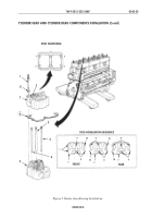
1.
Install new gasket (6) on cylinder head (5).
2.
Loosen six adjusting screws (2) three complete turns.
3.
Apply GO-80/140 lubricating oil to ball ends of four intake and exhaust pushrods (4) and two
injector pushrods (3).
NOTE
The injector pushrods are larger in diameter than the valve
pushrods. The valve pushrods are 0.007 in. (0.178 mm) longer
than injector pushrods.
Ensure each pushrod is installed in same position as noted
during removal.
Ball end of pushrods must fit into socket of cam followers. The
injector pushrod is installed on center injector cam follower.
4.
Install four intake and exhaust pushrods (4) and two injector pushrods (3) on cam followers of
cylinder head (5).
NOTE
Position six rocker levers so ball end of adjusting screw drops
into sockets of six pushrods.
5.
Install rocker arm housing (7) on cylinder head (5).
6.
Install six new washer bearings (8) on rocker arm housing (7).
NOTE
There are three different sizes of rocker housing studs. Install
correct rocker housing stud in correct rocker arm housing.
Damage to rocker housing stud threads may result if
substitution of length is made.
7.
Install six rocker housing studs (1), (9), and (10) on rocker housings (7) as shown in figure 3.
Tighten studs (1), (9), and (10) 65 lb-ft (68 N
•
m) in sequence shown in figure 3.
Back to Top


