TM-9-2815-225-34-P - Page 396 of 736
TM 9-2815-225-34&P
0044 00
0044 00-2
FUEL PUMP TESTING AND CALIBRATION (Contd)
WARNING
Allow adequate ventilation for engine exhaust gases. Do not
perform fuel system procedures while smoking or within 50 ft
(15.2 m) of sparks or open flame. Diesel fuel is flammable and
may explode. Failure to comply may result in serious injury or
death to personnel.
PREADJUSTMENT CHECKS
CAUTION
Do not alter pump settings to match gauges and tachometers of
unknown accuracy. Failure to comply may result in damage to
equipment.
NOTE
Vehicle fuel control lever and throttle stop linkage should have
a maximum throttle stop, so when fuel pump full throttle is
obtained, override pressure will not be on throttle shaft.
After proper calibration, fuel pump should require very little
adjustment. Some adjustment may be required at idle, since
this setting is dependent on parasitic loads. Fine adjustment of
governor settings and fuel manifold pressure is permissible
within the limits specified if justified by engine performance
tests.
Check and adjust throttle control linkage for full throttle
operation and throttle released operation with the throttle
stopped by the throttle leakage adjusting screw.
IDLE SPEED ADJUSTMENT
NOTE
Idle speed adjustment should never be made on a cold engine.
Engine must be operated for sufficient time to purge all air
from the fuel system and to bring the engine up to operating
temperature (at least 165° F (74° C) oil temperature).
1.
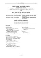
Remove plug (7) from spring pack cover (9) and start engine (1) on dynamometer (2).
NOTE
Fuel pump idle adjusting tool will not let the spring pack cover
leak when the idle is adjusted.
2.
Turn idle adjusting screw (16) in to increase engine rpm, out to decrease rpm.
3.
Using idle adjusting tool (4), set idle to 600 +/- 2 rpm.
4.
Install plug (7) on spring pack cover (9).
Back to Top


