TM-9-2815-225-34-P - Page 391 of 736
TM 9-2815-225-34&P
0043 00
0043 00-7
CYLINDER HEAD AND CYLINDER HEAD COMPONENTS INSTALLATION (Contd)
ROCKER ARM HOUSING (Contd)
NOTE
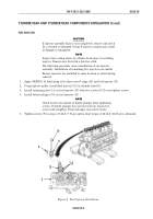
If torque driver ST-669 is used, tighten adjusting screw nut
40 lb-ft (54 N
•
m).
20.
Hold adjusting screw (9) in place and tighten adjusting screw nut (8) 45 lb-ft (61 N
•
m).
21.
Slowly rotate accessory drive pulley (1) clockwise until line in front of timing mark (3) aligns with
pointer (6) on front gear cover (5).
22.
Perform steps 10 through 16 for cylinder No. 6 injector.
23.
Perform steps 17 through 20 for cylinder No. 3 intake and exhaust valves.
24.
Slowly rotate accessory drive pulley (1) clockwise until line in front of timing mark (4) aligns with
pointer (6) on front gear cover (5).
25.
Perform steps 10 through 16 for cylinder No. 2 injector.
26.
Perform steps 17 through 20 for cylinder No. 6 intake and exhaust valves.
27.
Slowly rotate accessory drive pulley (1) clockwise until line in front of timing mark (2) aligns with
pointer (6) on front gear cover (5).
28.
Perform steps 10 through 16 for cylinder No. 4 injector.
29.
Perform steps 17 through 20 for cylinder No. 2 intake and exhaust valves.
30.
Slowly rotate accessory drive pulley (1) clockwise until line in front of timing mark (3) aligns with
pointer (6) on front gear cover (5).
31.
Perform steps 10 through 16 for cylinder No. 1 injector.
32.
Perform steps 17 through 20 for cylinder No. 4 intake and exhaust valves.
33.
Slowly rotate accessory drive pulley (1) clockwise until line in front of timing mark (4) aligns with
pointer (6) on front gear cover (5).
34.
Perform steps 10 through 16 for cylinder No. 5 injector.
35.
Perform steps 17 through 20 for cylinder No. 1 intake and exhaust valves.
Figure 4. Injector Timing.
11
10
9
8
5
6
7
1
2
3
4
Back to Top


