TM-9-2815-225-34-P - Page 386 of 736
TM 9-2815-225-34&P
0043 00
0043 00-2
CYLINDER HEAD AND CYLINDER HEAD COMPONENTS INSTALLATION (Contd)
CYLINDER HEAD
NOTE
The following procedure covers installation of one cylinder head
assembly. Installation of remaining cylinder heads is similar.
Perform steps 1 through 10 to install each additional cylinder
head assembly as required.
Ensure marks made on each cylinder head and cylinder block
during removal are matched together during installation so
that each cylinder head assembly is installed in its original
position on cylinder block.
Ensure new cylinder head gasket has the side with word TOP
facing upwards.
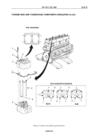
1.
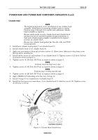
Install new cylinder head gasket (7) on cylinder head (5).
2.
Install cylinder head (5) on cylinder block (6).
3.
Apply rust preventative lubricant to twelve screws (4). Allow excess lubricant to drip from screw
threads before installation.
4.
Install twelve screws (4) and washers (3) on cylinder head (5). Tighten screws (4) 25 lb-ft (34 N
•
m)
in sequence shown in figure 1.
5.
Tighten screws (4) 100 lb-ft (136 N
•
m) in sequence shown in figure 1.
NOTE
Perform step 6 for Big Cam I only.
6.
Tighten screws (4) 305 lb-ft (414 N
•
m) in sequence shown in figure 1.
NOTE
Perform step 7 for Big Cam III only.
7.
Tighten screws (4) 285 lb-ft (387 N
•
m) in sequence shown in figure 1.
8.
Apply OE/HDO 10 lubricating oil to four new O-rings (8).
9.
Install O-rings (8) on counterbores of cylinder head (5).
10.
Install two fuel crossover connections (1) on cylinder head (5) with four screws (2). Tighten screws
(2) 38 lb-in (4.3 N
•
m).
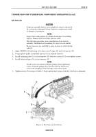
Figure 1. Cylinder Head Installation.
TIGHTENING SEQUENCE
6
5
7
8
1
2
3
4
I
L
K
J
F
B
E
H
D
A
C
G
Back to Top

