TM-9-2910-226-34 - Page 104 of 208
TM 9-2910-226-34
NOTE
Sub-paragraph (21) below applies to code A
pumps only.
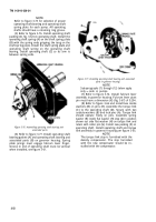
(21) Refer to figure 3-89 and install torque link
spring (A) from torque link pin to oil baffle.
Figure 3-89. Installing oil baffle, sliding sleeve and torque link
spring (code A pumps).
3-26. Repair of Governor Weight and Spider
Assembly.
a. Disassembly.
Disassemble the
governor friction drive as follows:
(1) Before any disassembly of the friction drive
assembly, check clearance between the governor
weight pin and weight pin bushing using a dial
indicator. Maximum allowable clearance is 0.003 -
inch with weights in their outermost position. If
clearance is greater than 0.003-inch, replace the
complete governor weight and spider assembly.
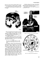
(2) Refer to figure 3-90. Place friction drive
spider (A) on a piece of 3/8 x ¾ steel stock held in
vise. Remove spring disk adjusting nut using socket
wrench (B).
NOTE
Early model friction drive spider assemblies
were assembled with a retainer. If retainer
(G, fig. 3-91) is removed at disassembly it
must be reinstalled at assembly. Later model
friction drive spider assemblies did not
utilize this part and reference to it can be
disregarded. Early code G pumps have a
special nut which requires use of spanner
wrench 5120-793-5046 for removal.
Figure 3-90. Removing or installing spring disk adjusting nut.
(3) Refer to figure 3-91. Remove outer spring
disk (B) spring disk spacer (C) inner spring disk (D)
and spring disk spacer (E) and retainer if used, from
friction drive spider.
Figure 3-91. Disassembling or assembling friction drive spider
and associated parts.
b. Inspection of Governor Weight and Spider
Assembly.
(1) Inspect the fingers on the spring disks (B
3-58
Back to Top


