TM-9-2910-226-34 - Page 108 of 208
TM 9-2910-226-34
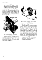
Figure 3-99. Identification of hydraulic head assembly
HD9070A (2910-084-0259).
a. Disassembly.
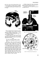
Refer to figure 3-100. Remove and
discard hydraulic head lower preformed packing (A)
and upper preformed packing (B). Do not remove
fuel inlet fitting.
3-62
Figure 3-100. Removing or installing hydraulic head packings.
b. Inspection.
Inspect the hydraulic head
assembly as follows:
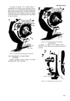
(1) Refer to figure 3-101. Examine plunger
button (A) and spring (B) for evidence of wear.
Check spring coils for breaks, cracks or distortion.
Check gear teeth (C) for wear patterns and chipped
or broken teeth.
Figure 3-101. Inspection of hydraulic head components.
Back to Top


