TM-9-2910-226-34 - Page 100 of 208
TM 9-2910-226-34
(11) Refer to figure 3-77 to insure that the spring
plate prongs have
engaged the fulcrum lever
assembly finger.
(12) Refer to figure 3-61. Install gasket (B) and
operating shaft bearing (A).
(13) Refer to figure 3-81. Install four bearing
mounting machine screws (A) and four copper
gaskets (B). Torque tighten screws 50-60 inch-
pounds and secure with locking wire.
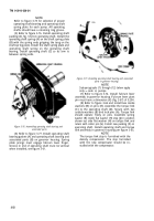
NOTE
Locking wire must be installed as shown to
avoid interference with movement of stop
lever.
Figure 3-81. Installing stop lever and associated parts.
NOTE
Sub -paragraphs (14) through (18) below do
not apply to code A pumps.
(14) Refer to figure 3-81. Install lever (C) with
slot alined with groove or scribe mark in end of
‘operating shaft. Install retaining ring (D). Hold stop
lever against retaining ring and install clamping
screw (E), and check clearance to obtain a tolerance
of 0.002 to O .004 -inch between stop lever and bearing
housing. If clearance is not within these limits,
replace operating shaft bearing housing. Torque
tighten clamping screw to 50-60 inch-pounds.
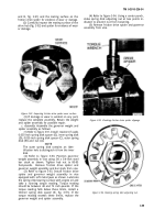
(15) Refer to figure 3-59 and install the
operating lever on operating shaft, and secure with
clamping screw (G), lockwasher (F) and hex nut (E).
Torque tighten nut to 70-75 inch-pounds. Position
lever as shown with split in lever alined with scribe
mark or groove on shaft as shown in figure 3-82.
Figure 3-82. Positioning operating levers.
(16) Refer to figure 3-83. Install idle adjusting
screw (A) and lock sleeve nut (B) with approximately .
5/32-inch of exposed thread at the bottom. Finger
tighten locknut. Install high speed adjustment screw
(C) with approximately 5/32-inch exposed thread at
the bottom. Install hex nut (D) and tighten finger
tight. Final adjustment of idle and high speed ad-
justment screws is made during calibration of the
pump.
3-54
Back to Top


