TM-9-2910-226-34 - Page 114 of 208
TM 9-2910-226-34
Section IV. ASSEMBLY OF FUEL INJECTION PUMP FROM SUBASSEMBLIES
3-34. General.
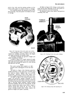
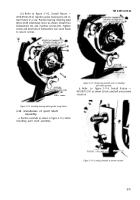
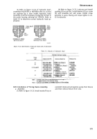
a.
Assembly of the metering and
distributing fuel inject ion pump should be performed
in figure number sequence and in accordance with
the instruct ions provided with each illustration.
b.
The fuel injection pump is a precision accessory
whose proper operation depends on cleanliness of all
parts. Precision lapped surfaces of rotating parts
must be free of dust and dirt at all times. During
assembly, keep working area, parts, hands, and
clothing clean.
c.
Immediately before assembly, coat all
bearings, shafts,
and contact surfaces with ap-
propriate engine oil. Always use new gaskets and
packings. Apply grease, Federal Specification W-P-
236, on tight fitting preformed packings to aid in
their installation.
3-35. Repair Kits.
a. General.
A number of repair
kits are supplied to repair the fuel injection pump.
Repair kits for the governor linkage, and timing
device unit assembly are listed in appendix B. The
kits were applied in the previous section during
assembly of the individual components.
The
KEY to fig 3-109
A
B
C
D
E
F
G
H
J
K
L
M
N
R
Timing device assembly
1/4x11/16 machine screw
Retaining plate lockwasher
Bearing retaining plate
Bearing retaining lock nut
Bearing retaining lockwasher
Camshaft ball bearing assembly
1 Bearing retaining ring
2 Camshaft ball bearing
Camshaft assembly
1 Camshaft
2 Assembled washer screw
Timing pointer
Tappet assembly
Plunger spring seat
Head lower preformed packing
Hydraulic head assembly
Stud sleeve
Hydraulic head nut
Head upper preformed packing
following are additional kits for repair of the fuel
injection pump.
b. Shim Set.
The shim set contains outer, and
inner spring spacers. The spacers are used to adjust
the governor inner and outer spring tensions. The
spacer set is listed in the repair list section in ap-
pendix B.
c. Gasket and Preformed Packing Set.
All
gaskets and preformed packings in the gaskets and
preformed packings set will be replaced during repair
of fuel injection pump.
3-36. Identification of Metering and Distributing
Fuel Injection Pump Components.
a. General.
To
identify, locate,
and show relationship of com-
ponents of the injection pump, refer to the exploded
views in the repair section of this chapter.
b. Exploded View Illustrations.
Figures 3-29
through 3-37, 3-70, 3-71, 3-97; and
injection pump and components.
illustrations to identify parts and aid
of the pump.
3-109 show the
Refer to the
in the assembly
T Plunger outer spring
U Injection pump housing assembly
1 Injection pump housing
2 Pump housing stud
3 Tappet guide pin
V 1/4x5/8 machine screw
W Copper gasket
X Governor weight and spider assembly
Y Quill shaft assembly
Z Quill shaft pad gasket
AA 1/4x5/8 machine screw
BB Copper gasket
CC Quill shaft pad cover
DD 3/8x1-1/4 machine screw
EE 3/8-inch lockwasher
FF 3/8-inch flat washer
CC Pump housing packing
HH Camshaft Woodruff key
JJ 3/8-inch lockwasher
KK 3/8x5-7/8 machine screw
P
Q
S Spring retaining ring
3-68
Back to Top


