TM-9-2910-226-34 - Page 122 of 208
TM 9-2910-226-34
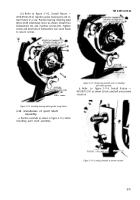
Figure 3-125. Removing fuel injection pump and fixture from vise.
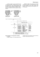
(2) Refer to figure 3-126. Lubricate and install
pump housing packing (A). Install timing device
hub (B) on camshaft, alining slot with woodruff key
(fig. 3-125). Install camshaft nut (C) and torque
tighten nut to 50-55 foot-pounds. Install camshaft
nut setscrew (D) and torque tighten setscrew to 25-
28 foot-pounds. Remove fixture from injection pump
housing.
Figure 3-126. Installing timing device hub on camshaft.
NOTE
It is possible to have pointer (A, fig. 3-108)
near the timing device hub scribe mark
without alinement of arrow and slotted tooth
being shown in the housing window (fig. 3-
122). If this occurs, rotate the timing device
hub one complete turn.
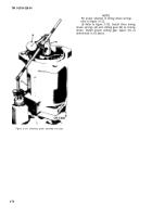
(3) Refer to figure 3-127. Install timing cover
gasket (A) and timing cover (B). Secure cover with
four machine screws (C) and lockwashers (D).
NOTE
If the fuel pump is to be tested immediately
after assembly, do not secure the timing
cover until adjustments are made as
described in paragraphs 3-50 through 3-58.
Figure 3-127. Installing timing cover.
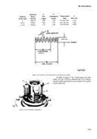
(4) Refer to figure 3-128. Install sliding gear (A)
on timing device hub. Select and fit proper sliding
gear spacer (B) to give 2.180 to 2.200-inch dimen-
sion. Remove sliding gear and sliding gear spacer
and retain for future assembly.
Figure 3-128. Selecting proper sliding gear spacer.
(5 Refer to figure 3-129. Install end play spacer
(A), spider assembly (B), and weight and spider
thrust plate (C) on camshaft.
3-76
Back to Top


