TM-9-2910-226-34 - Page 127 of 208
TM 9-2910-226-34
3-42. Installation of Governor Weight and Spider
Assembly.
NOTE
If a new governor weight and spider
assembly was drawn from supply, or if it is a
serviceable part, refer to figure 3-93 and
check friction drive spider slippage; it must
be 48-73 pound-inches.
a.
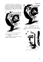
Refer to figure 3-137. Before installing, check
weight and spider assembly extreme-open position
(A). Extreme-open position (A) should not exceed
3.380 inches. If the open position exceeds this limit,
replace complete assembly. After completing check,
position injection pump housing (B) on an arbor
press and position weight and spider assembly (D)
on camshaft (C). Position remover and replacer over
camshaft and press weight and spider assembly onto
camshaft until flush with shoulder.
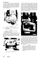
Figure 3-137. Checking extreme open position of governor
weight and spider assembly and installing
assembly using remover and replacer.
b.
Refer to figure 3-138. Check camshaft run-out.
Run-out should not exceed 0.003-inch. If camshaft
run-out is between 0.003 to 0.005-inch straighten
camshaft by suitable means. Replace the camshaft if
camshaft cannot be straightened.
Figure 3-138. Checking camshaft run-out.
c.
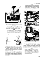
Refer to figure 3-139. Check sliding sleeve
travel. Remove sliding sleeve from governor
housing, figure 3-89. Position sliding sleeve (A) in
governor weight and spider assembly and rotate
weights (B) completely outward
(a
above) 3.380-inch
(maximum). Sliding sleeve travel must be a
minimum of 0.630-inch. If travel is less than 0.630 -
inch, replace governor weight and spider assembly.
Install sliding sleeve in governor housing, figure 3-
89.
Figure 3-139. Checking sliding sleeve travel.
3-81
Back to Top

