TM-9-2910-226-34 - Page 120 of 208
TM 9-2910-226-34
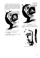
(3) Refer to figure 3-121. Position compressor
and secure with two stud sleeves (A) and hydraulic
head nuts (B). Turn thumb screw (C) clockwise to
compress plunger spring seat. Install spring
retaining ring (D) using suitable pliers. Release
spring tension by turning thumb screw coun-
terclockwise and remove the compressor.
Figure
3-121. Installing tappet spring retaining ring
using compressor.
3-40. Installation of Hydraulic Head Assembly.
NOTE
For proper selection of hydraulic head
assemblies refer to table 3-2.
a. Assembly.
The hydraulic head was inspected
and assembled during repair (para 3-28).
b. Installation.
CAUTION
Do not force the hydraulic head into the
housing. A slight pressure will be required to
seat the preformed packings in the housing.
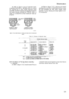
(1) Refer to figure 3-122. Position hydraulic
head assembly (A) on injection pump housing so
plunger sleeve slot faces opening, and aline slotted
tooth of plunger drive gear with arrow on injection
pump housing. Install four stud sleeves (B) and
hydraulic head nuts (C). Torque tighten nuts to 18-
20 foot-pounds.
Figure 3-122. Installing hydraulic head assembly.
NOTE
Sub-paragraphs (2), (3), and (4) below apply
to code F and G pumps only.
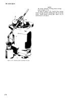
(2) Refer to figure 3-123. Install filter screw
copper gasket (A) and oil filter (B) on filter screw
(D). Apply grease, Federal specification VV-P-236,
to filter screw packing (C), and install on oil filter
screw (D). Install oil filter screw and associated
parts. Torque tighten screw to 20-25 foot-pounds.
Figure 3-123. Installing oil filter.
3-74
Back to Top


