TM-9-2910-226-34 - Page 121 of 208
(3)
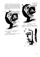
Refer to figure 3-124. If hydraulic head ,
(4) Refer to figure
TM 9-2910-226-34
3-123. Lubricate and install
assemblies HD9070A or HD9085A with an oil duct
packing (G) on pin-(H). Install washer (E) on screw
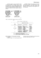
are replaced by a later model hydraulic head
(F) and assemble pin and screw. Install screw
assembly, it will be necessary to plug the oil duct in
assembly in pump housing and torque tighten to 20-
the pump housing utilizing kit 5704374. Refer to
25 foot-pounds.
table 3-2 to determine correct hydraulic head ap-
plication.
Figure 3-124. Identification of hydraulic heads with oil lubrication
ducts.
Table 3-2. Selection of Hydraulic Head
3-41.
Installation of Timing Device Assembly.
camshaft. Remove fuel injection pump from fixture
a. Assembly.
and then remove fixture from vise.
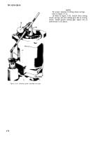
(1) Refer to figure 3-125. Install woodruff key on
3-75
Back to Top


