TM-9-2910-226-34 - Page 126 of 208
TM 9-2910-226-34
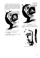
Figure 3-134. Installing spider assembly, spacer, and thrust plate.
b.
Installation.
Install the timing device
assembly as follows:
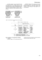
(1) Refer to figure 3-135. Install bolt (F) in
pump and timing device housing before assembly of
timing device housing to pump housing. Install
timing device housing (A), after checking to see if
pump housing packing is in position, and secure with
two flat washers (B), lockwashers (C), and machine
screws (D). Torque tighten machine screws to 17-20
foot-pounds. Install housing packing (E).
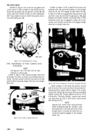
Figure 3-135. Installing timing device housing.
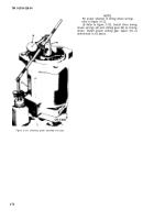
(2) Refer to figure 3-136. Install pipe-to-tube
elbow (C), pipe-to-tube tee (B), and oil distribution
hose assembly (A).
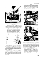
Figure 3-136. Installing oil distribution hose assembly and fittings.
3-80
Back to Top


