TM-9-6920-430-14 - Page 97 of 180
TM 9-6920-430-14
Do not attempt to assemble protective barrier with fewer than four men.
Each panel weighs 120 lbs and will require two men to position assemblies in
place.
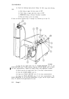
(21) To assemble the proof pressure test protective enclosure, position panel
assemblies (19), (20), (21), and (22) around GPU as shown.
(22) Center panel assembly (19) to assure equal front and rear spacing. Proper
positioning of this panel will correctly locate the remaining panels (20), (21), and (22).
(23) When side panel (19) has been correctly positioned, raise into place and
hold in position.
(24) Raise front panel assembly (22) and reposition as required so that
overlapping hinge slots (23) are properly aligned.
(25) Insert hinge pins (24).
(26) Raise remaining panels (20) and (21) respectively and align hinge slots for
insertion of hinge pins as described in steps 24 and 25 above.
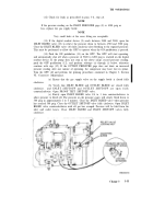
(27) When the protective enclosure is in place, carry the digital readout device
and control box as far beyond the protective barrier as allowed by the control cables. Be
sure area is cleared of other personnel.
High gas pressure (up to 8000 psig) exists at the GPU when performing the
procedure below. Death or severe injury may result if you fail to follow
instructions — if the proof test fails at any time during the procedure you
will probably hear a loud noise or explosion or a loud hiss of gas escaping. A
rapid decrease in pressure on the digital readout device is also an indication
of proof test failure. If a failure occurs:
(1) immediately release override button on the control box;
(2) remain in a position sheltered from the GPU, and;
(3) do not allow anyone to approach the GPU for at least 30 minutes.
After 30 minutes, shut down the GPU in accordance with paragraph 3-9,
page 3-44.
(28) At the maximum distance permitted by the cable, hold the control box in
your hand and position the digital readout so that you can read it.
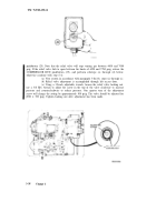
(29) Start the operation of the GPU by pressing and holding the black
pushbutton labeled COMPRESSOR RUN (25) on the control box. This button must be
held down for the GPU to continue operating until the relief valve opens.
(30) Hold the COMPRESSOR RUN pushbutton down, while observing the
increasing pressure displayed on the digital readout device, until the GPU relief valve
opens between 6550 and 7250 psig. The escaping gas may be heard when the relief valve
opens, and the digital readout device will begin to indicate a decrease in pressure. Record
the pressure at which the relief valve opens and release the COMPRESSOR RUN
Change 3
3-37
Back to Top


