TM-9-6920-430-14 - Page 94 of 180
TM 9-6920-430-14
(d) Remove housing enclosure in accordance with paragraph 3-l8, steps a
through c.
(e) On S4, loosen the locking setscrew that holds the pressure adjustment
screw using a 3/32-inch hex wrench.
(f) Using a large flatblade screwdriver, turn the adjustment screw
counterclockwise to lower or clockwise to raise the pressure. Tighten locking set screw.
One eighth turn will change the pressure by approximately 250 psig. Adjust S4 to shut the
pump off at 6000 ± 200 psig.
(g) Replace housing enclosure in reverse order of removal para. 3-18c.
(h) Check results of S4 adjustment by performing procedures in accordance
with paragraph 3-7, steps (1) through (36), and paragraph 3-8a, steps (1) through (14). If
another adjustment is necessary, turn off the pump by depressing S2 OFF switch and
repeat steps (a) through (h).
(i) If S4 cannot be adjusted within tolerance, replace S4 in accordance with
instructions in paragraph 3-22.
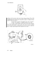
(15) If the INLET PRESSURE (8) and the OUTLET PRESSURE (2) gages do
not read within ± 100 psig of the digital readout (9), perform steps (16) through (18) to
correct out of tolerance gage; otherwise, go to step (19).
(16) Loosen knob on gage cover and remove glass assembly from gage.
NOTE
Not all GPUs have locking screws (13); if not present, disregard reference to
(13).
(17) Using a small flatblade screwdriver, loosen screw (13). Adjust screw (14) to
match reading on digital readout, then tighten screw (13).
(18) Replace the glass assembly and tighten the attaching screw.
3-34
Change 3
Back to Top


