MWO-5-2350-262-35-4 - Page 112 of 207
MWO 5--2350--262--35--4
4--9
SECTION II INSTALLATION OF NEW FORWARD LEFT MANIFOLD
ASSEMBLY -- CONTINUED
4--3
FORWARD LEFT MANIFOLD FUNCTIONALITY TESTING -- CONTINUED
c.
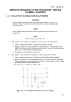
Testing hydraulic circuit port 11 (side of manifold) to ports 11A and 11B on the top of the manifold.
1. Connect transducer test cable to T10.
2. Connect --6 pressure hose with 37
_
flare fitting to port 11 on the side of the manifold.
3. Connect valve test cable from the 28 VDC power supply to valves V3 and V9. Do not energize
the power supply at this time.
4. Pressurize port 11 hose to 1000 psig (6894.757 kilopascal) and flow of approximately 5 GPM
(18927.06 CPM) and verify flow is exiting from ports 11A and 11B and there is no fluid flowing
from any other manifold ports.
5. Energize the 28 VDC power supply and verify the flow from ports 11A and 11B has stopped.
6. Read the voltage at T10.
7. De--pressurize hose and de--energize the 28 VDC power supply.
8. Disconnect --6 pressure hose from port 11 and disconnect valve test cables from valves V3 and
V9. Disconnect T10 transducer cable.
9. This completes manifold functionality test.
Back to Top


