MWO-5-2350-262-35-4 - Page 111 of 207
MWO 5--2350--262--35--4
4--8
SECTION II INSTALLATION OF NEW FORWARD LEFT MANIFOLD
ASSEMBLY -- CONTINUED
4--3
FORWARD LEFT MANIFOLD FUNCTIONALITY TESTING
CAUTION
Testing should be performed in a clean environment and protective dust covers or caps
should be installed on all openings to prevent contamination. Dirt can damage parts and
cause malfunctions.
NOTE
Prior to installing the primary manifold in vehicle, the following functionality tests should
be performed.
NOTE
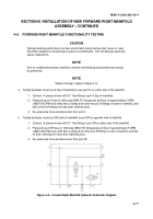
Steps a through c apply to Figure 4--3.
a.
Testing of hydraulic circuit port 9 (top of manifold) connected to two port 9’s on either side of the
manifold.
1. Connect --6 pressure hose with 37
_
flare fitting to port 9 (top of manifold).
2. Pressurize the port 9 hose to 1000 psig (6894.757 kilopascal) and a flow of approximately 5
GPM (18927.06 CPM) and verify flow is exiting from the other two port 9 fittings on the sides of
the manifold, and that there is no fluid flowing from any other manifold ports.
3. De--pressurize hose and disconnect from port 9.
b.
Testing hydraulic circuit port 3L (side of manifold) to port 3L on the opposite side of the manifold.
1. Connect --8 pressure hose with 37
_
flare fitting to port 3L on either side of the manifold.
2. Pressurize the port 3L hose to 1000 psig (6894.757 kilopascal) and a flow of approximately 5
GPM (18927.06 CPM) and verify flow is exiting from the port 3L fitting on the other side of the
manifold and there is no other fluid flowing from any other manifold ports.
3. De--pressurize hose and disconnect from port 3L.
Figure 4--3. Forward Left Manifold Hydraulic Schematic Diagram
Back to Top


