MWO-5-2350-262-35-4 - Page 127 of 207
MWO 5--2350--262--35--4
4--24
SECTION IV INSTALLATION OF AFT MANIFOLD ASSEMBLY -- CONTINUED
4--12 ASSEMBLY OF HDC AFT MANIFOLD
CAUTION
Assembly should be performed in a clean environment and protective dust covers or
caps should be installed on all openings to prevent contamination. Dirt can damage
parts and cause malfunctions.
CAUTION
When securing aft manifold in vice, exercise extreme care not to mar any surfaces or
damage components.
CAUTION
Do not over torque. Failure to comply may result in damage to equipment.
NOTE
Steps a through e applies to Figure 4--13.
NOTE
A vice must be used to secure the aft manifold during assembly.
NOTE
Refer to Section I, Table 1--7, Aft Manifold Parts List, for required parts.
a.
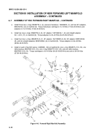
Install on four NO valves, 12496925, (1), and one NC valve, 12496926 (16), one o--ring, MS28775--118,
(2), one backup, MS27595--019, (3), one o--ring, MS28775--019, (4), and one backup, MS27595--019, (3)
on manifold (10).
b.
Install two new o--rings, MS28778--6, (6), 90
±
adapter, MS51527A6, (5) and straight adapter,
MS51525A6, (9) on manifold (10). Torque 90
±
adapter to 22--24 ft/lbs (29.82--32.53 N
S
m).
c.
Install new o--ring, MS28778--8, (7) and plug, 12335054--5, (8) on manifold (10). Torque plug to 40--43
ft/lbs (54.23--58.30 N
S
m).
d.
Install two new o--rings, MS 28788--12, (11) and two straight adapters, MS51525A12, (12) on manifold
(10). Torque adapters to 68--75 ft/lbs (92.19--101.68 N
S
m).
e.
Install two new o--rings, MS28778--4, (9), straight adapter, MS51525A4, (14), and 90
±
adapter,
MS51527A4, (14) on manifold (10). Torque adapters to 13--15 ft/lbs (17.62--20.33 N
S
m).
Back to Top


