SMI-9-2320-387-14P-1 - Page 203 of 671
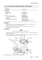
11-67.6. REAR GUN MOUNT PLATE ASSEMBLY REPLACEMENT
This task covers:
a. Removal
b. Installation
a. Removal
1.
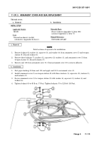
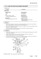
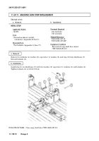
Remove three locknuts (7), washers (3), reinforcement brackets (6), capscrews (2), and washers (3)
from rear plate assembly (4) and cargo floor (5). Discard locknuts (7).
2.
Remove three locknuts (8), washers (9), capscrews (1), washers (9), and rear plate assembly (4) from
cargo floor (5). Discard locknuts (8).
3.
Remove 40 mm gun mount support (para. 11-67.8) and caliber .50 gun mount support
(para. 11-67.7) from rear plate assembly (4).
INITIAL SETUP:
Applicable Models
M1151
Tools
General mechanic’s tool kit:
automotive (Appendix B, Item 1)
Materials/Parts
Six locknuts (Appendix G, Item 106)
Personnel Required
One mechanic
One assistant
Manual References
TM 9-2320-387-10
TM 9-2320-387-24P
Equipment Condition
Rear end of cargo shell door raised
(TM 9-2320-387-10).
b. Installation
1.
Install caliber .50 gun mount support (para. 11-67.7) and 40 mm gun mount support (para. 11-67.8)
on rear plate assembly (4).
2.
Install rear plate assembly (4) on cargo floor (5) with three washers (3), capscrews (2),
reinforcement brackets (6), washers (3), and locknuts (7).
3.
Secure rear plate assembly (4) to cargo floor (5) with three washers (9), capscrews (1), washers (9),
and locknuts (8). Tighten capscrews (1) and (2) to 26 lb-ft (35 N
•
m).
FOLLOW-ON TASK: Close cargo shell door (TM 9-2320-387-10).
SMI 9-2320-387-14&P-1
Change 4
11-128.7
Back to Top

