SMI-9-2320-387-14P-1 - Page 322 of 671
This task covers:
a. Removal
b. Installation
Manual References
TM 9-2320-387-10
TM 9-2320-387-24P
Equipment Condition
Battery ground cable disconnected (para. 4-68).
a. Removal
b. Installation
1.
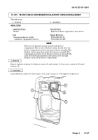
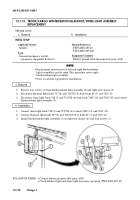
Remove four screws (1) from blackout/dome light assembly (3) and right end closure (2).
2.
Disconnect blackout light leads 717 (8) and 711/712 (9) from leads 2C (7) and 711C (6).
3.
Disconnect dome light leads 719 (5) and 711/712 (4) from leads 719C (10) and 712C (11) and remove
blackout/dome light assembly (3).
1.
Connect dome light leads 719 (5) and 711/712 (4) to leads 719C (10) and 712C (11).
2.
Connect blackout light leads 717 (8) and 711/712 (9) to leads 2C (7) and 711C (6).
3.
Install blackout/dome light assembly (3) on right end closure (2) with four screws (1).
SMI 9-2320-387-14&P-1
12-174
Change 4
FOLLOW-ON TASKS: • Connect battery ground cable (para. 4-68).
• Check blackout light and dome light for proper operation (TM 9-2320-387-10).
NOTE
• Replacement instructions for left and right blackout/dome
light assemblies are the same. This procedure covers right
blackout/dome light assembly.
• Prior to removal, tag leads for installation.
INITIAL SETUP:
Applicable Models
M1152
Tools
General mechanic’s tool kit:
automotive (Appendix B, Item 1)
12-113. TROOP/CARGO WINTERIZATION BLACKOUT/DOME LIGHT ASSEMBLY
REPLACEMENT
Back to Top

