SMI-9-2320-387-14P-1 - Page 316 of 671
1.
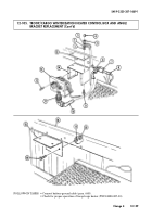
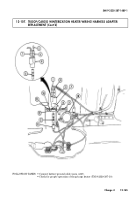
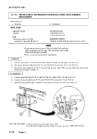
Remove four screws (22) and upper side channel (23) from left end closure (24).
2.
Remove ten screws (26) and lower side channel (25) from left end closure (24).
3.
Remove four screws (19) and right blackout/dome light assembly (1) from right end closure (27).
4.
Disconnect harness leads 712C (7) and 719C (6) from dome light leads 711/712 (8) and 719 (9).
5.
Disconnect harness leads 711C (2) and 2C (3) from blackout light leads 711/712 (5) and 717 (4).
6.
Remove four screws (21) and left blackout/dome light assembly (10) from left end closure (24).
7.
Disconnect harness leads 712B (13) and 719B (14) from dome light leads 711/712 (12) and 719 (11).
8.
Disconnect harness leads 711B (16) and 2B (15) from blackout light leads 711/712 (17) and 717 (18)
and remove wiring harness (20).
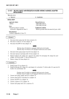
This task covers:
a. Removal
b. Installation
INITIAL SETUP:
Applicable Models
M1152
Tools
General mechanic’s tool kit:
automotive (Appendix B, Item 1)
Manual References
TM 9-2320-387-10
TM 9-2320-387-24P
Equipment Condition
• Battery ground cable disconnected (para. 4-68).
• Cargo floor cover removed (para. 12-115).
• Blackout/dome light switch removed
(para. 12-111).
• Blackout/dome light door switch removed
(para. 12-112).
SMI 9-2320-387-14&P-1
12-168
Change 4
a. Removal
NOTE
Prior to removal, tag leads for installation.
12-110. TROOP/CARGO WINTERIZATION BLACKOUT/DOME LIGHT WIRING HARNESS
REPLACEMENT
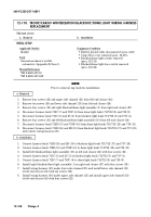
b. Installation
1.
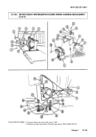
Connect harness leads 711B (16) and 2B (15) to blackout light leads 711/712 (17) and 717 (18).
2.
Connect harness leads 712B (13) and 719B (14) to dome light leads 711/712 (12) and 719 (11).
3.
Install left blackout/dome light assembly (10) on left end closure (24) with four screws (21).
4.
Connect harness leads 711C (2) and 2C (3) to blackout light leads 711/712 (5) and 717 (4).
5.
Connect harness leads 712C (7) and 719C (6) to dome light leads 711/712 (8) and 719 (9).
6.
Install right blackout/dome light assembly (1) on right end closure (27) with four screws (19).
7.
Install wiring harness (20) under lower side channel (25) and install lower side channel (25)
to left end closure (24) with ten screws (26).
8.
Install wiring harness (20) under upper side channel (23) and install upper side channel (23)
to left end closure (24) with four screws (22).
Back to Top

