TB-9-1000-234-13 - Page 31 of 52
TB 9-1000-234-13
B-1
APPENDIX B
RECOIL EXERCISER INSTRUCTIONS
Table B-1.
Materials
Item Number
National Stock Number
Description
(U/M)/(U/I)
1
Cloth, abrasive crocus, 50 sheets
PG
2
Fluid, hydraulic (MILPRF6083) (81349)
GL
3
Sealant, pipe, teflon 12297953 (19207)
TU
4
Wood, 4x4 MM-L-751 (81348)
FT
B-1
Installation
WARNING
•
Cylinder support assembly weighs 85.7 pounds (38.87 kg). Two individuals are
required to position and install cylinder support assembly to prevent injury to personnel.
•
Ensure cylinder support assembly is held in place until front and rear lower shoes are
installed and the assembly has been slid towards the dust cover for a snug fit to
prevent personnel injury.
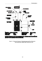
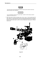
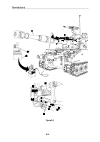
1. Position cylinder support assembly (1) on top of cannon tube (2), so that the upper front yoke (3) is
15 inches (38.1 cm) behind the bore evacuator (4) (see figure B-1).
NOTE
Do not force fit cylinder support assembly on cannon tube.
2. Install lower front shoe (5) and secure with two flat washers (6) and two screws (7) finger tight.
3. Install lower rear shoe (8) and secure with two flat washers (9) and two screws (10) finger tight.
4. Slide cylinder support assembly (1) towards dust cover (11) until there is a snug fit.
Back to Top

