TB-9-1000-234-13 - Page 35 of 52
TB 9-1000-234-13
B-5
B-2
Operation
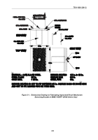
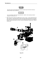
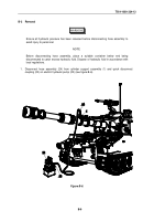
1. Release cannon tube (2) from travel lock (25) and position cannon tube at the same elevation as
when held by travel lock. Slow travel lock (see figure B-4).
2. Place chalk markings on cannon tube (2) 12 and 14 inches (30.4 and 35.5 cm) from front of dust
cover (5).
•
Breech must be closed prior to pumping to prevent damage to operating cam rollers.
•
Longer of the two recoil exerciser cable assemblies must clear top plate of the replenisher
(M109A6).
3. Close breech (29).
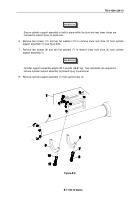
WARNING
Cylinder support assembly has moving parts. Keep clear of cylinder support assembly
during operation to avoid injury.
NOTE
•
The electric hydraulic pump has a three position REMOTE ON-OFF-MOMENTARY ON
switch. To operate the electric hydraulic pump using the remote control, place the
REMOTE ON-OFF-MOMENTARY ON switch in the REMOTE ON position. To operate
the electric hydraulic pump without the remote control, hold the REMOTE ON-OFF-
MOMENTARY ON switch in the MOMENTARY ON position.
•
Make sure quick disconnect couplings are fully seated.
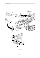
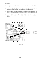
4. If using electric hydraulic pump (22), place manual valve (27) in upright position. Using the electric
hydraulic pump, begin pumping. During pumping, check for hydraulic leaks. If leaks are found,
slowly release hydraulic pressure and replace defective parts (see figure B-5).
5. Continue pumping until front of dust cover (5) is between the chalk markings.
6. Inspect buffer piston rod (28) for discoloration. If no discoloration is found, skip to step 9.
CAUTIONs
Back to Top

