TB-9-2320-279-13-P-2 - Page 68 of 460
Change 1
0012 01-2
TB 9-2320-279-13&P-2
DOOR HANDLE ASSEMBLY REPLACEMENT - MODEL B - CONTINUED
0012 01
REMOVAL - CONTINUED
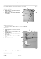
4.
Remove spring pin (9), outside handle (10), shaft (11),
and nut (15) from door (1).
5.
Remove bolt (13), washer (14), and padlock bracket
(12) from door (1).
CLEANING AND INSPECTION
Clean and inspect all parts IAW
General Maintenance Instructions
(WP 0011 00).
INSTALLATION
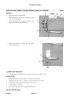
1.
Install padlock bracket (12), washer (14), and bolt (13)
on door (1).
2.
Install shaft (11), nut (15), outside handle (10), and
spring pin (9) on door (1).
3.
Install nut (5), cam (7), inside handle (4), and spring
pin (6) on door (1).
4.
Connect link rod (2) and install new locknut (8) on
cam (7).
5.
Connect spring (3) to cam (7).
6.
Verify correct operation of door assembly (WP 0004 00).
END OF WORK PACKAGE
440-063
Back to Top


