TB-9-2320-280-35-15 - Page 39 of 168
TB 9-2320-280-35-15
5-15
10-3.
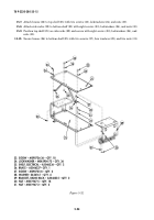
Attach control cable (5) to MT-6353/VRC mounting base (1).
10-4.
Attach power cable (6) to MT-6353/VRC mounting base (1).
10-5.
Route cables (5) and (6) through hole in back of integrated rack (3).
NOTE
Ensure control cable and power cable are routed through hole in
back of integrated rack before installing MT-6353/VRC mounting
base.
10-6.
Attach MT-6353/VRC mounting base (1) to integrated rack (3) with four capscrews (9) and (10), four
lockwashers (8), and nut strip (7).
Figure 5-21.
Figure 5-22.
7. NUT STRIP – A3014064-1 – QTY. 1
8. LOCKWASHER – MS45904-72 – QTY. 4
9. CAPSCREW – B1821BH031F125N – QTY. 2
10. CAPSCREW – B1821BH031F075N – QTY. 2
5
1
6
5. CONTROL CABLE – A3210672-1 – QTY. 1
6. POWER CABLE – A3154857-1 – QTY. 1
3
7
1
10
8
8
9
Back to Top


