TB-9-2320-302-13-P-1 - Page 308 of 380
Installation Manual – P/N 0257550622-00
(Doc No.:
II
113500-1 D)
Freightliner M915 / M916 -
Crew Protection Kit
Page 116 of 125
4.
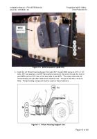
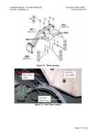
Lift part #007 into position as shown in Figure 7-8.
Insert the aft-most bolts (Item 22).
Temporarily use the aft fasteners to hold the deflector in position.
Install the center and
forward fasteners next with the 113513-3 and 113513-1 spacers respectively (do not
tighten the bolts until all fasteners are in place).
Apply thread-locking compound to the
bolts.
Install the hardware in the following order:
• Star Washer
• Flat Washer
• Insert bolt from beneath through assembled parts
• Flat Washer
• Nut.
5.
Tighten bolts to a 122-Nm (90 lb-ft) torque.
6.
Ensure that the flexible brake lines are not rubbing on the inside lower edge of the wheel
zone deflector (#007).
If the lines are rubbing near the Wheel Zone Deflector, it may be
possible to relocate them by loosening the hose end fitting, twisting the lines slightly, and
then re-tightening the hose end fittings.
7.
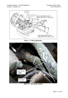
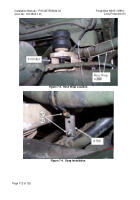
Apply protective hose wrap to the flexible brake lines in the area shown in Figure 7-9.
Back to Top

