TB-9-2320-302-13-P-1 - Page 315 of 380
Installation Manual – P/N 0257550622-00
(Doc No.:
II
113500-1 D)
Freightliner M915 / M916 -
Crew Protection Kit
Page 123 of 125
7.7 Rear Wall Mounting Plate (M915-A2 and M916-A1)
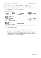
This step should be performed after Step 5-11 and prior to Step 5-17 in the main installation sequence.
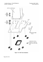
7.7.1 Parts, Fasteners, Special Tools, and Materials
Parts
(see Figure 7-12):
Part No.
Alternate
Part No.
Description
Find No. in
Procedure
Quantity
113507-1
Plate, Mounting
#507
1
Fasteners
: (see Figure 7-12)
Find No.
(Table 3-5)
Description
Size
Quantity
4
Bolt
5/16” x 1-1/4”
6
58
Screw, self tapping
#10
16
Special Tools
:
Description
Vendor/Part-Number
No 21 drill bit (0.159” Diameter)
8.7.2 Installation Instructions
1.
Remove the six bolts indicated in Figure 7-12 and install part #507 using new bolts (4) and
existing washers.
Apply thread-locking compound to the screws.
2.
Original Equipment Manufacturer (OEM) components that were displaced from the rear
wall may now be mounted to this plate.
Simply transfer the mounting hole pattern for
each component to the plate and drill a 0.159” (No. 21) hole for each mark.
Secure the
component with #10 x ½” self tapping screws (58).
Back to Top

