TB-9-2320-302-13-P-1 - Page 311 of 380
Installation Manual – P/N 0257550622-00
(Doc No.:
II
113500-1 D)
Freightliner M915 / M916 -
Crew Protection Kit
Page 119 of 125
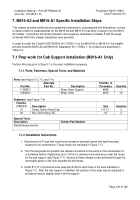
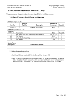
7.5 Shift Tower Installation (M915-A2 Only)
This procedure may be performed anytime after step 5.4 in the installation process.
7.5.1 Parts, Fasteners, Special Tools, and Materials
Parts
(see Figure 7-10):
Part No.
Alternate
Part No.
Description
Find No. in
Procedure
Quantity
113511-1
Adapter, Shift Tower
#511
1
Fasteners
: (see Figure 7-10)
Find No.
(Table 3-5)
Description
Size
Quantity
4
Bolt (these bolts were temporarily used in step 5)
5/16” x 1-1/4”
5
25
Flat Washer
5/16”
5
56
Screw, Button Head Cap
1/4” x 1/2”
8
32
Flat Washer
1/4”
8
Special Tools
:
Description
Vendor/Part-Number
7.5.2 Installation Instructions
1.
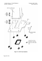
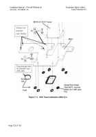
Bolt the shift tower adapter #511 to the Center Floor Armor # 815.
2.
Feed the shifter cable up through the square hole in the center floor panel and the adapter
plate.
Re-attach the shift cable to the shift tower and bolt the shift tower to the shift tower
adapter part #511 (see Figure 7-10).
Apply thread-locking compound to the screws.
Back to Top

