TB-9-2320-302-13-P-1 - Page 91 of 380
TB 9-2320-302-13&P-1
WHEEL ZONE DEFLECTOR REPLACEMENT - CONTINUED
0018 00
0018 00-3/(0018 00-4 Blank)
REMOVAL - CONTINUED
3.
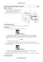
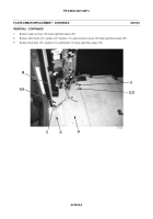
Using lifting device, remove six nuts (8), bolts (9),
washers (10), star washers (11), bracket (7), and wheel
zone deflector support arm (5) from bumper.
4.
Remove sling and lifting device from wheel housing
(5).
CLEANING AND INSPECTION
Clean and inspect all parts IAW
General Maintenance Instructions
(WP 0011 00).
INSTALLATION
1.
Attach sling and lifting device to wheel zone deflector support arm (5).
WARNING
Use extreme caution when handling heavy parts. Provide adequate support and use assistance during proce-
dure. Ensure that any lifting device used is in good condition and of suitable load capacity. Keep clear of
heavy parts supported only by lifting device. Failure to follow this warning may cause injury or death to per-
sonnel.
NOTE
•
Door assembly weighs 368 lb (167 kg).
•
Align wheel zone deflector support arm and bracket to allow wheel zone deflector to clear truck hood.
2.
Using lifting device, install wheel zone deflector support arm (5), bracket (7), six washers (10), star washers (11), bolts
(9), and nuts (8) on bumper.
WARNING
Use extreme caution when handling heavy parts. Provide adequate support and use assistance during proce-
dure. Failure to follow this warning may cause injury or death to personnel.
3.
With assistance, install wheel zone deflector (6), six washers (2), star washers (3), bolts (4), and nuts (1) on wheel zone
deflector support arm (5).
END OF WORK PACKAGE
417-157
8,9,10,11
7
5
Back to Top

