TB-9-2510-251-13 - Page 175 of 624
2-159
TB 9-2510-251-13
4
3
5
2-2.1
Installation of Air Conditioning Kit to M998 and M998A1; M1037; M1097 and M1097A1
Two-Door with O’Gara Hess Add-on-Armor (Cont’d).
d. Install Refrigerant Hoses (Cont’d)
(6)
Compressor to condenser, #8 hose:
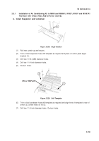
Route hose through rear grommet (outside vehicle) and forward along driver’s side frame
rail.
Continue forward and outboard of parking brake linkage and up into engine
compartment near oil filter and dipstick.
Route hose around rear of valve covers to
passenger side of engine and forward to compressor.
Leave approximately two feet of
hose sticking up from grommet.
(7)
Evaporator to compressor, #12 hose:
Route hose through grommet and forward along driver’s side frame rail.
Continue forward
and outboard of parking brake linkage and up into engine compartment near oil filter and
dipstick.
Route hose around rear of valve covers to passenger side of engine and forward
to compressor.
Leave approximately two feet of hose sticking up from grommet.
CAUTION
•
Avoid high heat surfaces, sharp edges, and moving parts of vehicle.
Keep
hoses tucked up high enough to prevent being snagged as vehicle travels over
obstacles or brush.
Failure to comply could result in damage to equipment.
•
Hoses should span no more than two feet without being secured.
Failure to
comply could result in damage to equipment.
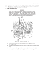
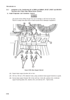
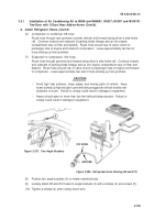
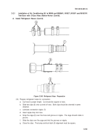
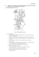
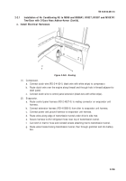
Figure 2-237.
Two Angle Brackets
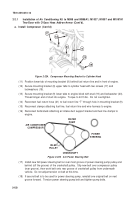
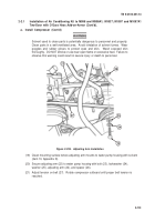
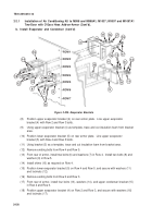
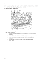
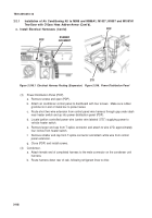
#8 HOSE
#12 HOSE
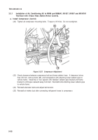
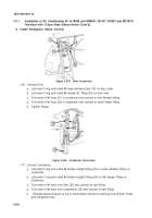
Figure 2-238.
Refrigerant Hose Routing (#8 and #12)
(8)
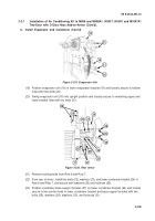
Position two angle brackets (3) on intake manifold studs.
(9)
Loosely attach #8 and #12 hoses to angle brackets (3) with p-clamps (4) and screws (5).
(10)
Tighten p-clamps (4) after routing clutch wire.
Back to Top

