TB-9-3950-253-13-P
PALLETIZED LOAD SYSTEM TRUCK, M1075 and M1075A1 (PLS) AND HEAVY EXPANDED MOBILITY TACTICAL TRUCK, M1120, M1120A2, AND M1120A4 (HEMTT), ENHANCED CONTAINER HANDLING UNIT (E-CHU)
TECHNICAL BULLETIN; OPERATOR AND FIELD MAINTENANCE, INSTALLATION INSTRUCTIONS, AND REPAIR PARTS AND SPECIAL TOOLS LIST
JULY 2009
TB-9-3950-253-13-P - Page 400 of 704
TB 9-3950-253-13&P
0040-2
0040
REMOVAL
00040
WARNING
•
Twistlock assembly will fall when roller pin is removed. Use caution and support twistlock
assembly while removing roller pin.
•
Twistlock housing will swing when roller pin is removed. Use caution and support twistlock
housing while removing roller pin.
•
Failure to follow these warnings may result in injury to personnel.
NOTE
•
Perform steps 1 through 4 for both right and left sides.
•
Note location of spacers to aid in installation.
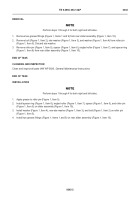
1. Remove locking pin (Figure 1, Item 6) from rear slider bed (Figure 1, Item 1).
2.
With assistance, support twistlock housing (Figure 1, Item 8) and twistlock assembly (Figure 1, Item 7) and
remove bolt (Figure 1, Item 2), washer (Figure 1, Item 3), roller pin (Figure 1, Item 4), two spacers (Figure 1,
Item 5), and twistlock assembly from rear slider bed (Figure 1, Item 1).
3. Remove clip (Figure 1, Item 10) from locking pin (Figure 1, Item 9).
4. While supporting twistlock housing (Figure 1, Item 8), remove locking pin (Figure 1, Item 9) and twistlock
housing from rear slider bed (Figure 1, Item 1).
Figure 1.
Twistlock Assembly.
040
END OF TASK
CLEANING AND INSPECTION
00040
Clean and inspect all parts IAW WP 0020,
General Maintenance Instructions
.
END OF TASK
1
2
3
4
5 (HIDDEN)
6
7
8
9
10
Back to Top


