TM-5-2350-377-14-P - Page 184 of 335
TM 5-2350-377-14&P
DISASSEMBLY
NOTE
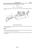
Steps 1 through 6 applies to Figure 76.
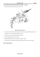
1. Remove ten control box power harness connectors ( item 9) from
coil connectors (item 8).
Figure 76.
Rear Fuel Tank Strap.
2. Remove tee (item 7), reducer (item 6), and tee (item 5) from elbow (item 4) on track and blade manifold (item 1),
port T.
3. Remove elbow (item 4) from track and blade manifold (item 1), port P.
4. Remove two straight adapters (item 2) from tee (item 3).
5. Remove tee (item 3) from track and blade manifold (item 1), port BR.
6. Remove straight adapter (item 2) from track and blade manifold ( item 1), port BL.
TRACK AND BLADE MANIFOLD ASSEMBLY REPLACEMENT
0029 00
0029 00-1
INITIAL SETUP
Tools/Test Equipment
Tool kit, general mechanic's
(Item 6, WP 0056 00)
Materials/Parts:
Lubricating oil (Item 15, WP 0055 00)
Caps and plugs (Item 6, WP 0055 00)
Cleaning solvent (Item 7, WP 0055 00)
Equipment Conditions
Right, center, and left rear floor plates removed
(TM 5-2350-262-10)
Hydraulic system pressure relieved
(TM 5-2350-262-20-1)
Hydraulic hoses removed (WP 0027 00, Disassem-
bly)
Back to Top

