TM-5-2350-377-14-P - Page 187 of 335
TM 5-2350-377-14&P
TRACK AND BLADE MANIFOLD ASSEMBLY REPLACEMENT - continued
NOTE
Step 3 applies to Figure 80.
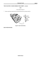
3. Install three straight adapters
(item 12) on track and blade manifold bottom (item 1), ports CR1, CR2, and CL1.
Figure 80.
Rear Fuel Tank Strap.
NOTE
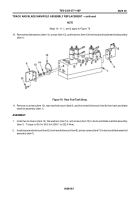
Step 4 applies to Figure 81.
4. Use suitable lifting device to lift front manifold mount (item 8), rear manifold mount (item 9),
and track and blade
manifold (item 1) to hole in hull wall and attach with four screws (item 10).
Figure 81.
Rear Fuel Tank Strap.
0029 00
0029 00-4
12
12
12
1
9
1
8
10
11
10
Back to Top


