TM-5-2350-377-14-P - Page 180 of 335
TM 5-2350-377-14&P
TRACK ADJUSTING CYLINDER ASSEMBLY REPLACEMENT - continued
ASSEMBLY
NOTE
Steps 1 through 5 apply to both cylinders.
Step 1 and 2 apply to Figure 71.
1. If new cylinder, install lubrication fitting (item 13) and plug (item 18) on fixed end of hydraulic track adjusting cylinder
(item 4), so that lubrication fitting (item 13) faces forward and ports (item 16 and 17) face upward.
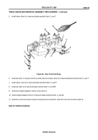
Figure 71.
Track Adjusting Cylinder.
2. If new cylinder, iremove plug (item 15) and install lubrication fitting (item 14) on rod end of hydraulic track adjusting
cylinder (item 4) so that lubrication fitting (item 14) faces rearward.
NOTE
Coat threads of screw and nut with lubricating oil prior to installation.
Screw must be inserted from bottom when connecting fixed end of cylinder to hull.
Step 3 applies to Figure 72.
3. With ports (item 16 and 17) pointing up, connect fixed end of hydraulic track adjusting cylinder (item 4) to hull mounting
bracket (item 11) with pin (item 8), washer (item 7), screw (item 12), washer (item 7), and new locknut (item 6).
Figure 72.
Track Adjusting Cylinder Rod End.
0028 00-3
0028 00
14
13
15
16
17
4
18
12
8
6
7
17
4
11
16
7
Back to Top


