TM-5-2350-377-14-P - Page 181 of 335
TM 5-2350-377-14&P
TRACK ADJUSTING CYLINDER ASSEMBLY REPLACEMENT - continued
NOTE
There is an additional clamp on left hydraulic track adjusting cylinder.
Coat threads of screw and nut with lubricating oil prior to installation.
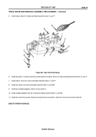
Step 4 applies to Figure 73.
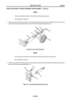
4. Connect rod end (item 5) of hydraulic track adjusting cylinder (item 4) to final drive adjusting flange (item 10) with
pin (item 8), washer (item 7), screw (item 9), washer (item 7), and new locknut (item 6).
Figure 73.
Final Drive Adjusting Flange.
NOTE
Step 5 and 6 applies to Figure 74.
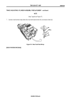
5. Tighten locknuts (item 6) to 19 to 31 lb-ft (39 to 42 N•m).
6. Lubricate bearings (item 19) with grease at lubrication fittings (item 13 and 14).
Figure 74.
Track Adjusting Cylinder Locknuts.
14
19
19
6
6
13
0028 00-4
0028 00
7
9
10
7
8
5
4
6
Back to Top


