TM-5-2350-378-24-P - Page 184 of 790
TM 5--2350--378--24&P
0011 00--13
EJECTOR CREEPS -- Continued
0011 00
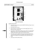
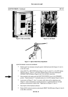
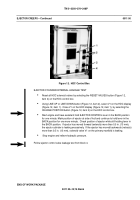
Figure 9. HDC Control Box
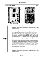
Figure 10. DCV Bank
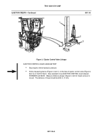
Figure 11. Ejector Relief Valve Adjustment
EJECTOR RELIEF VALVE ADJUSTMENT
Disable ejector by manually closing the ejector inhibit ball valve V23 (Figure 10, item 1)
on the DCV bank.
Using LINE UP or LINE DOWN button (Figure 9, item 3), select V1 on the HDC display
(Figure 9, item 2). Close V1 on the HDC display (Figure 9, item 2) by selecting the
CHANGE POSITION button (Figure 9, item 4) on the HDC control box.
Have assistant start engine and hold EJECTOR CONTROL lever in the FORWARD
position. Read transducer T--2 hydraulic pressure on the HDC display (Figure 9, item 1).
Loosen jam nut (Figure 11, item 1) on ejector relief valve and turn adjusting screw
(Figure 11, item 2) clockwise (to increase pressure) or counterclockwise (to increase
pressure) until pressure is within limits. Tighten jam nut (Figure 11, item 1).
Stop engine; relieve hydraulic pressure.
Reset all HDC solenoid valves by selecting the RESET VALVES button (Figure 9, item 5)
on the HDC control box.
Back to Top


