TM-5-2350-378-24-P - Page 588 of 790
TM 5--2350--378--24&P
0034 00--3
REPLACE HDC PRIMARY MANIFOLD ASSEMBLY AND MOUNTING BRACKET --
Continued
0034 00
REMOVAL -- CONTINUED
4.
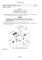
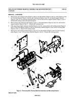
Remove two self--locking screws (Figure 2, item 6), two flat washers (Figure 2, item 5), screw (Figure 2, item
8), three flat washers (Figure 2, item 9), self--locking nut (Figure 2, item 12), and lateral support bracket
(Figure 2, item 13) from primary manifold (Figure 2, item 4) and hull floor support bracket (Figure 2, item 7).
Discard self--locking screws and self--locking nut.
5.
Remove three self--locking screws (Figure 2, item 11), three flat washers (Figure 2, item 10), and hull floor
support bracket (Figure 2, item 7). Discard self--locking screws.
6.
Fully supporting weight of primary manifold (Figure 2, item 4), remove seven self--locking screws (Figure 2,
item 2), seven flat washers (Figure 2, item 3), and primary manifold (Figure 2, item 4) with mounting plate
(Figure 2, item 1). Discard self--locking screws.
7.
Remove four self--locking screws (Figure 2, item 15), four flat washers (Figure 2, item 14), and mounting
plate (Figure 2, item 1) from primary manifold (Figure 2, item 4). Discard self--locking screws.
Figure 2. Removing HDC Primary Manifold Assembly and Mounting Bracket
END OF TASK
Back to Top


