TM-5-2350-378-24-P - Page 604 of 790
TM 5--2350--378--24&P
REPLACE VALVE V21 (V22), RELIEF VALVE, AND BYPASS HOSE -- Continued
0036 00
INSTALLATION -- CONTINUED
6.
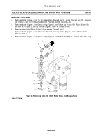
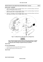
Install new o--ring (Figure 4, item 2) and adapter (Figure 4, item 1) on relief valve (Figure 4, item 3) and
attach to bulkhead bracket (Figure 4, item 10).
7.
Install new o--ring (Figure 4, item 9) and adapter (Figure 4, item 8) on relief valve (Figure 4, item 3) and
attach tee (Figure 4, item 7) to adapter (Figure 4, item 8).
8.
Install new o--ring (Figure 4, item 6) and adapter (Figure 4, item 5) on relief valve (Figure 4, item 3) and
attach bypass hose (Figure 4, item 4) to adapter (Figure 4, item 5).
Figure 4. Installing Valve V21 (V22), Relief Valve, and Bypass Hose
WARNING
Ensure right main hydraulic pressure inhibit valve V22 is fully opened prior to starting
vehicle. A fully or partially closed valve will cause immediate high pressure. Failure
to comply may result in damage to equipment and injury to personnel.
END OF TASK
FOLLOW--ON MAINTENANCE
1.
Install filter guard protective bracket (TM 5--2350--262--20--2).
2.
Restore hydraulic pressure (TM 5--2350--262--10).
END OF TASK
END OF WORK PACKAGE
0036 00--5/6 blank
Back to Top

